> For the complete documentation index, see [llms.txt](https://andrea-santis-organization.gitbook.io/andrea-santi-mdef-course/llms.txt). Markdown versions of documentation pages are available by appending `.md` to page URLs; this page is available as [Markdown](https://andrea-santis-organization.gitbook.io/andrea-santi-mdef-course/year-1/term-1/_-digital-fabbrication.md).
# !\_! \\\Digital Fabbrication
It was a course during all the first Term, we learned a lot of new fabbrication's practice. \
From Arduino, to use all the machine in the Fab Lab: Cnc Mill and 3D print, Laser Cut. \
We also spend time, me and max a lot, in Wood lab. The course is centered in learning the workflow that made model start from the determinate machine.
We are developing a continuos modus operandi: we controlled tools to connect digital design in physical. This thanks a circulare connection between prototype, concept and design.
### ARDUINO
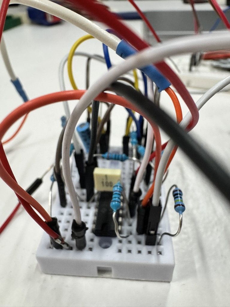
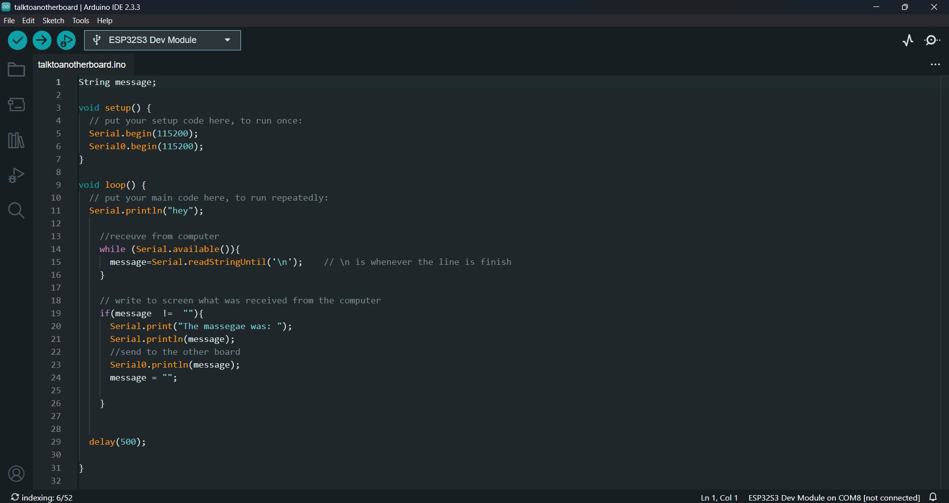
Thanks to MDEF''s Arduino Team, we learned how to use BARDUINO that is a more user-friendly arduino developed here in IAAC (easy board). Barduino is a physical computing trough building interactive systems, to try bridge the gap between enviroment and elettronic systems. In Arduino we have Digital (INPUT \\\high low) and Analog (0-4095 \\\12 bits) signals, this two are connecting with Pulse widht modulation that is a square waves explain the connection between this two different signals.
Barduino was important in Machine parodox course and in Funky Fungi interventions. \
I don't have a lot of skill in this practies, I really want to learn more and more.
### CNC MILL
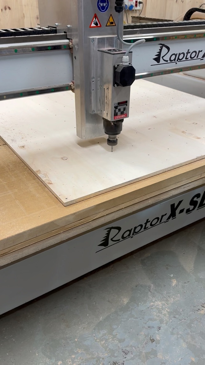
A CNC mill is a precision machine that uses computer-controlled instructions (G-code) to cut and shape materials. Key parameters include spindle speed, feed rate, cutting depth, tool diameter, and material type.
Funny(design) moments with the guy, attached the plate on the CNC's bed
#### Using a CNC Mill:
1. **Design the Part**: Create the design in a CAD software (like Rhino).
2. **Generate G-code**: Convert the design into machine-readable G-code using CAM software (e.g., RhinoCAM).
3. **Setup the Machine**: Secure the workpiece, install tools, and zero the machine.
4. **Run the Machine**: Load the G-code and begin machining, monitoring the process for adjustments.
5. **Finishing**: Clean and finalize the part.
#### Using Rhino with CNC Mills:
1. **Create the Design**: Model the part in Rhino.
2. **Prepare the Model**: Ensure the design is solid and ready for machining.
3. **Generate Toolpaths**: Use RhinoCAM or other CAM software to define the toolpath and create G-code.
4. **Run the CNC Mill**: Load the G-code to the CNC mill and start machining.
Rhino helps in creating precise 3D models, while CAM software converts these into machining instructions for the CNC mill.
I became a meme ^+ ^+ °--
This digital machine was important to create the modules for Design Dialogues, but I didn't use a lot so I would improve a lot my skill in this fantastic machine.
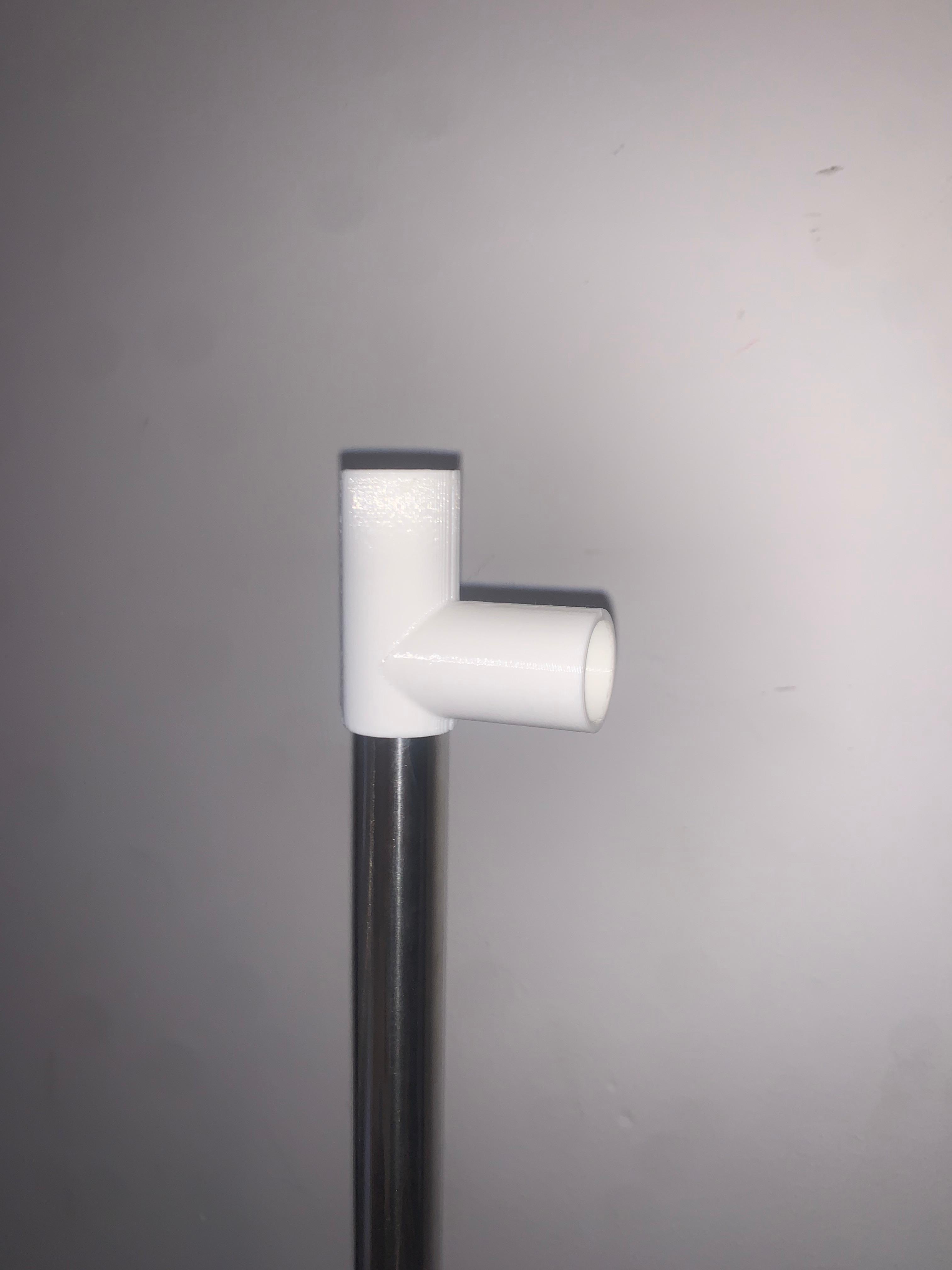
### 3D PRINT
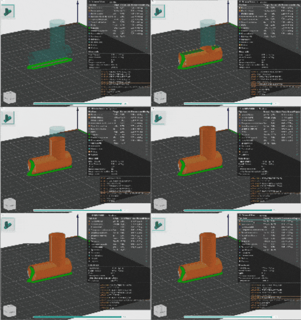
3D printing is a process of making three-dimensional objects by building them layer by layer from a digital design. It turns a virtual model into a physical object using materials like plastic, metal, or resin.\
In 3D printing, several parameters influence the quality, speed, and accuracy of the printed object. These parameters include:
1. **Layer Height (Resolution)**:\
This defines the thickness of each layer of material that is deposited during printing. A smaller layer height results in finer detail and a smoother surface but takes more time to print.
2. **Orinetation**:\
The orentation of the pieces to print is important for the print's timing. Also is so important for the tension create in the object and material waste.
3. **Infill Pattern**:\
The design of the internal structure, which can be solid, honeycomb, grid, or others. Different patterns offer varying strength, material use, and print time.
4. **Shell Thickness (Wall Thickness)**:\
The thickness of the outer walls of the printed object. Thicker shells give strength to the object but use more material.
5. **Support Structures**:\
Supports are temporary structures printed along with the object to help with overhangs or complex geometries. They can be removed after printing but may leave marks.
This digital machine was important for Machine parodox and groups design intervention.
### LASER CUT
Laser Cut is a digital machine that works in a substractive way thanks to an input geometry, this one give as a result an outcome thanks to vectors and rasters. \
The files (input) has to follow this process, diveved by layer and color:
1. **Engraving**:\
The laser removes a thin layer to create deeper designs or text, often used for permanent markings.
2. **Marking**:\
The laser makes light surface changes (like discoloration) without cutting or engraving, used for adding text or logos.
3. **Cut (inside//outside)**:\
The laser fully penetrates the material to separate it into pieces, creating precise cuts.
Are so important two modus operandi: Nesting (optimize space\\\nowaste material) and Tollerance test (always understand material's size and cut). \
Also is releated how you set the plate in the machine, has to be flat and you have always to adjust the distance between the lens and the material; if you have somethings really particular you can adjust the lens.
You have a lot different laser cut methodologies: Shape segmentation, Develop surface, Stacking, Interlocking, Waffle, Kerfing, Laminating
This digital machine was important for Machine parodox and groups design intervention.
## TOUCH DESIGNER
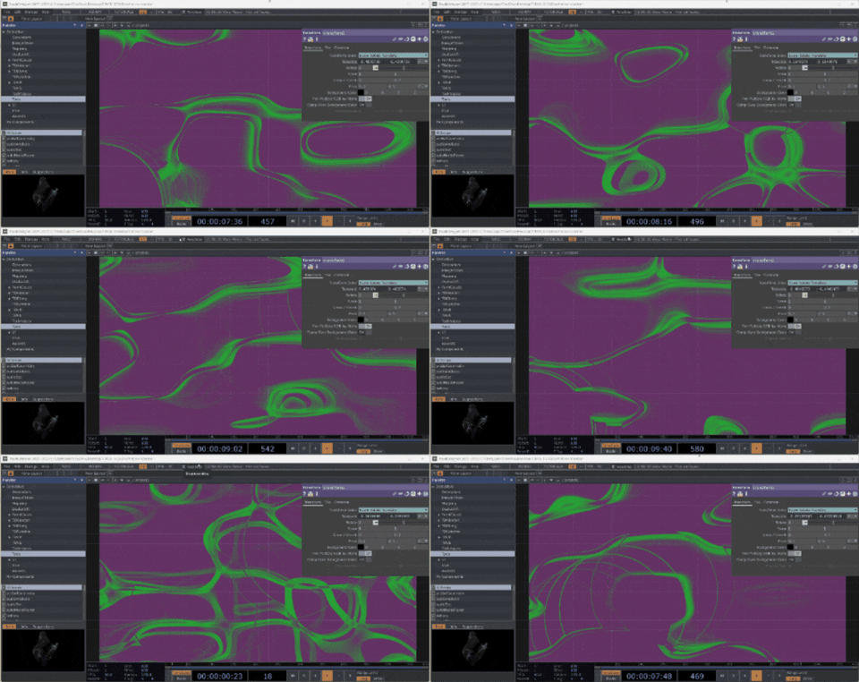
Touch designer is a visual programming software used for creating interactive media systems, real-time graphics, and multimedia installations. Is a visual programming software, you can maneged Input (data sensor) in animation visual. \
Input's type:
* **Motion sensor**:
* **Capacitive sensor**:
* **Button controller**:
* **Music**:
* **Project mapping**:
* **Generative IA**:
## \\\ MDEF BOARD
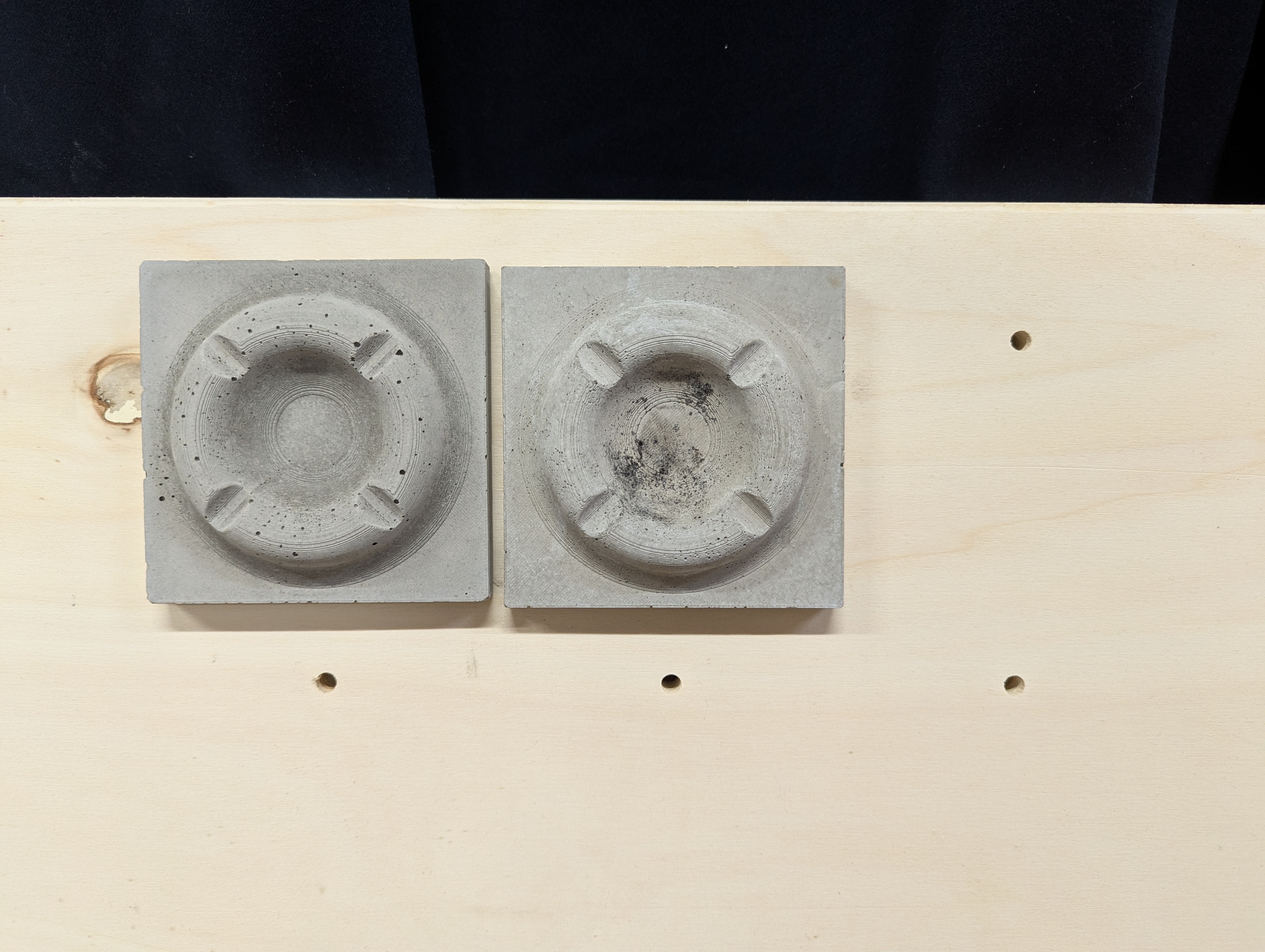
It was an exercise to understand how works a mold, Didac tell us to develop a tiles that would be mold in different material. We split in different groups, so the board in our class has different type of tiles made off different material.
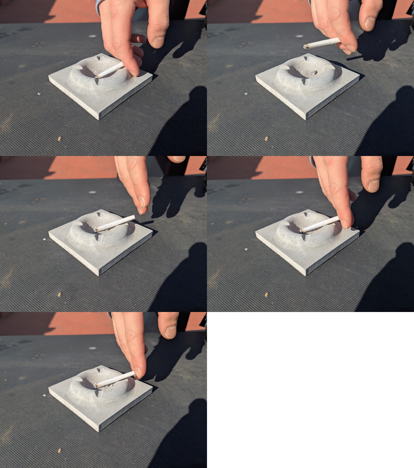
I was in group with David and we develop an hastray, its shape is armonic and we made it with concrete due to its functionallity.
The process for made this tile has this 3 step:
1. **3D print**:\
Choose and design what would be mold, we made a 3D model on Rhino an we print it
2. **Create the mold**:\
With the 3D print tiles, we made a sylicon mold. Thanks to sylcon put insede an cardboard box made with laser cut
3. Mold:\
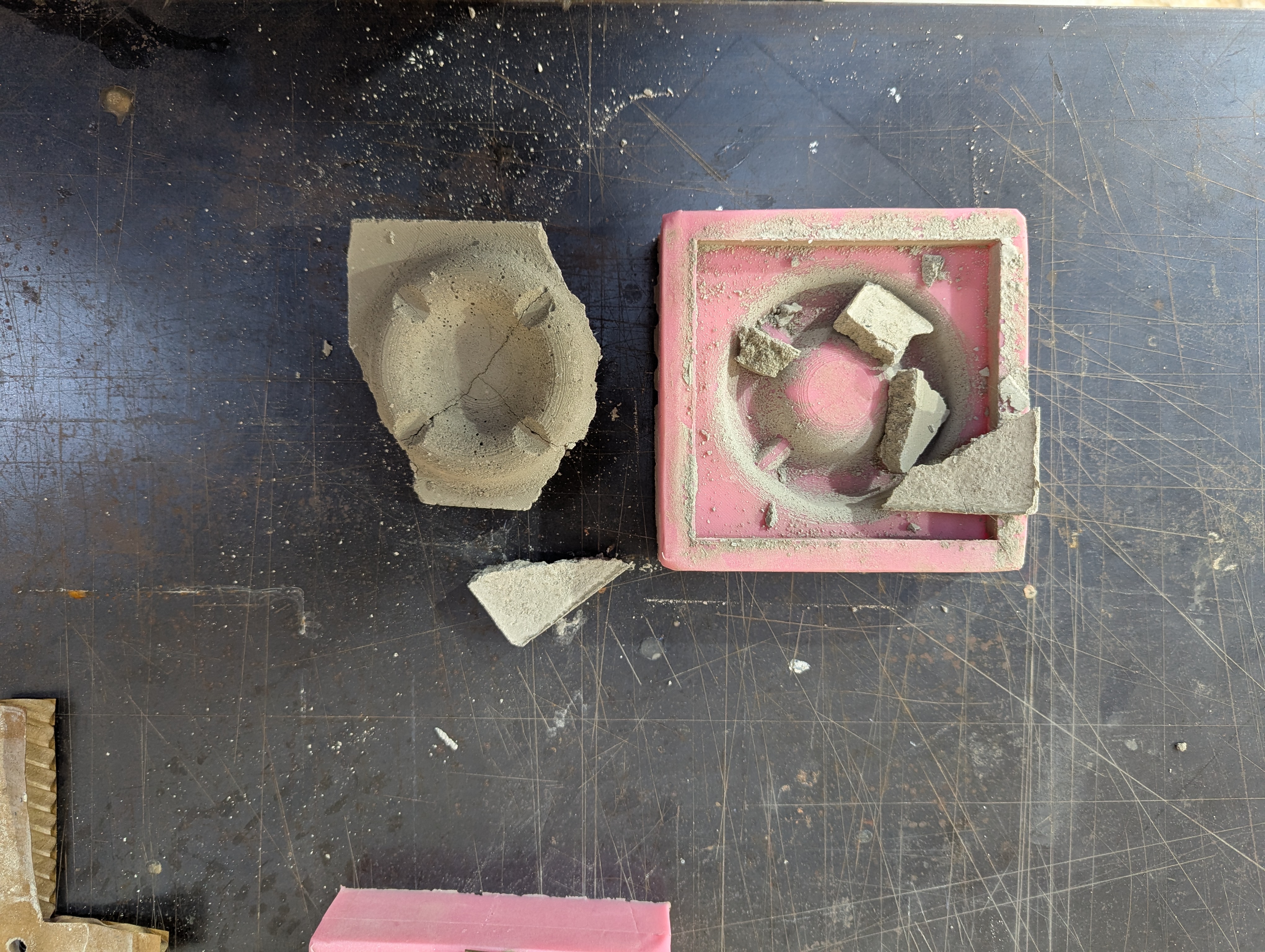
We insert concrete in the mold
***
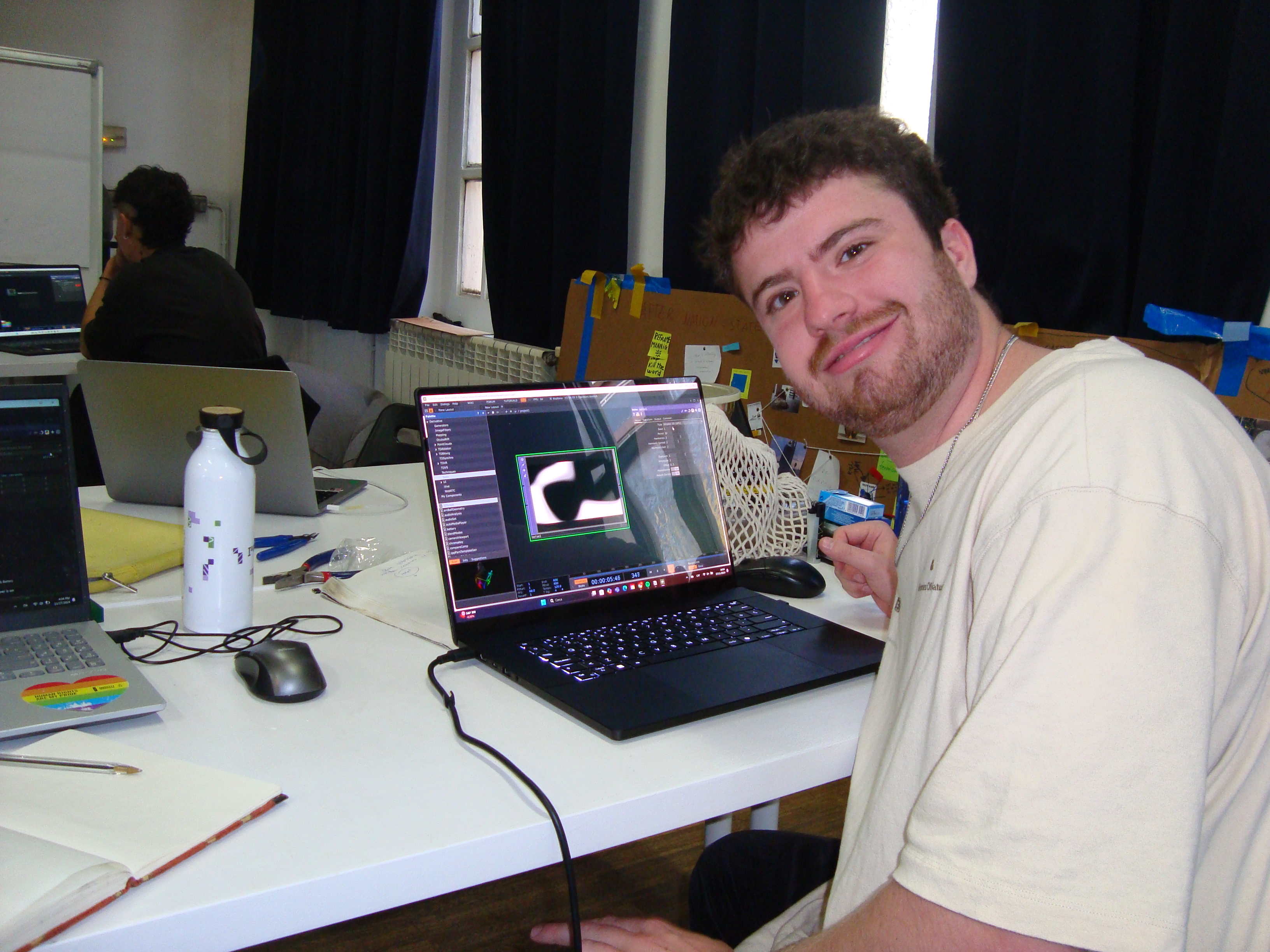
Some photo during digital fabbrication course, what an amazing group of funny people!!!